Еще одна схемка найденная мной на просторах интернета. Схема представляет собой, часть заряда АКБ , и вторую часть включение освещения когда на улице зашло солнце. Данную роль выполняет фото резистор LDR1. Далее стоит реле которым управляет фото резистор. не знаю зачем городить такую схему когда можно поставить 12в реле по выходу с СБ и оно бы само отключалось когда на улице нет солнца. Хотя посмотрев по внимательней реле скорей всего отключает нагрузку когда заряд АКБ падает. Вся схема управляется ICL7665, даташит на нее можно глянуть тут http://www.datasheetcatalog.org/datasheets2/11/116987_1.pdf ,микропроцессор который и следит как за зарядом АКБ так и за освещением.
На двух других схемах вы можете выбрать варианты подключения и зарядки АКБ. В принципе данную схему так же можно отнести и к контроллерам заряда АКБ, если ее немного под редактировать. Так же доработав схему, и добавив в нее, датчик движения мы увеличиваем ее применение и срок службы АКБ. За счет включения Света только тогда, когда он нужен.

для людей которым важно описание вот оригинал:
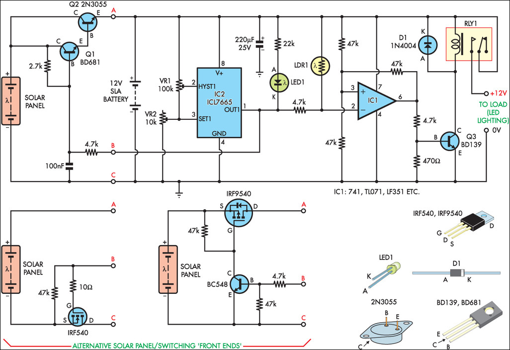
This circuit is based on a 10W solar panel and 12V SLA battery which powers an array of LED lamps for a pergola. It uses the ICL7665 over/under voltage detector to prevent overcharge and over-discharge of the battery and to provide control of the supply to the LEDs.
Individual solar lights sold these days for garden applications don’t seem to last too long before deteriorating and the light output can be low to unusable. The downside of this circuit is that the lamps/LEDs all have to be hard-wired to a common supply. On the upside, all contacts are soldered for reliability and only one battery is required.
During daylight hours, the diode-protected monocrystalline solar panel delivers about 550mA at up to 21V, with peak power efficiency at around 17V. Only one half of IC2, an ICL7665, is used. It is preset to detect 14.1V and 10.8V via 10-turn trimpots VR1 and VR2. This is accomplished by detecting the nominal trigger voltage at SET1 (pin 3) of 1.35V and using the chip’s internal hysteresis at HYST1 (pin 2).
To begin, assume that the Darlington-connected emitter-follower transistors Q1 & Q2 are conducting. As the battery charges up, the voltage eventually rises to 14.1V, whereupon pin 1 of IC2 switches from high to low. This turns on LED1 and switches off Q1 & Q2 (biased via the 4.7k? resistor to pin 1). This effectively disconnects the solar panel input to the SLA battery, thereby preventing overcharging.
Pin 1 of IC2 also attempts to pull pin 2 of IC1 low via the 4.7k? resistor. However, LDR1’s low daylight resistance, in the order of a couple of hundred ohms, ensures the voltage on pin 2 remains high.
IC1 is connected as a comparator with pin 3 held at approximately 1/2VCC by two 47k? resistors. As dusk approaches, LDR1’s resistance slowly rises to the megohm range and the voltage on pin 2 slowly falls to below the level at pin 3, whereupon IC1’s output at pin 6 switches from low to high. This turns on Q3, energising the relay and connecting the positive supply to the load.
The battery slowly discharges through the load until one of two events occurs. When dawn arrives, LDR1’s resistance drops as the ambient light increases, IC1’s output switches low and Q3 switches off the relay. This also reconnects the solar panel via Q1 & Q2 to recharge the battery.
Alternatively, some time during the night the battery will discharge to IC2’s detection point of 10.8V whereupon IC2’s pin1 switches high, switching off LED1 and toggling IC1 so that Q3 switches off and de-energises the relay. The discharged battery voltage then floats up to around 12.6V and as Q1 & Q2 have also been switched on again, the unit then waits for the charging cycle from the solar panel the next day.
A point to note is that the battery must fully discharge, with IC2’s output triggering high (LED1 off), before recharging through Q2 can commence. So it is important not to set the discharge voltage detection point too low, ie, no lower than 10.8V. More information on battery discharge/charge parameters can be found in the article entitled Micropower Battery Protector in the July 2004 issue of SILICON CHIP.
LED1 should be a high-brightness type so that the modest current allowed by the 22k? limiting resistor (about 750µA) will give adequate indication. The circuit is quite efficient, drawing only about 3-5mA in the off/ready state and about 35mA is required to activate the standard DPDT relay
Colin O’Donnell,
Glenside, SA.
так же ссылка на оригинал тут :http://www.siliconchip.com.au/cms/A_111702/article.html